GM relies heavily on injection-molded plastic in all its vehicles, with each one containing several hundred injection-molded parts. These parts change dramatically with each new model introduction, requiring engineers to develop new designs and molds to make the parts.
But developing a design and mold for a production-quality part costs hundreds of thousands of dollars and often requires several iterations at the mold tryout and verification stages before arriving at a part with the right size, shape, stiffness, and strength. To transform this "make it and break it" part development process, GM R&D initiated a major effort during the 1990s to understand the process of producing injection-molded parts. (See Figure 1.)
Figure 1. Design and processing knowledge is organized into interrelated areas.
Injection molding involves converting plastic into products by injecting melted resin, often containing glass fibers, into cavities of complex shape under high pressure. (See figure 2.)
Figure 2. The injection molding process uses thermoplastic resin fed into a combination screw feed, heat, and injection unit. The resin melts and mixes as it feeds into the space between the end of the screw and injection nozzle. Then the injection unit forces the melted plastic through a nozzle and into the mold. As the resin in the mold freezes, the screw rotates to melt and feed in more material and the cycle is repeated.
A key part of the effort to clarify what occurs during injection molding was an Advanced Technology Program (ATP) called TED, short for Thermoplastic Engineering Design. The program had several main goals:
- Develop comprehensive mechanics-based design knowledge
- Incorporate the knowledge in engineering tools
- Demonstrate the technology in applications
One of the key outcomes was the coupling of flow analysis - how the manufacturer makes the part - with structural analysis - how the part performs in its final form.
"At the beginning of the ATP, the state of the art in injection
molding involved a two-part process for flow and structural
analysis," says
Howard
Cox, Lab Group Manager, Composites Processing. "We would
start with flow analysis to design the mold and determine
where the gates should go. Then we took the part design and
determined if it would perform under appropriate conditions.
Now we've combined these two analyses."
Why is the combination so critical? "In injection molding, fibers orient during flow," explains Cox. "The material becomes anisotropic: It has different mechanical properties in different directions. That has to be brought into the structural analysis or you'll get an incorrect result - and a part that doesn't perform as expected."
To reveal the relationship between processing conditions and materials characteristics, the researchers began by molding plaques under very controlled processing conditions. "We monitored and recorded as many processing variables as we could," says Charles Mentzer, Staff Research Engineer, who led the experimental effort. "We then measured and evaluated the plaques, looking at many different properties: dimensions and warpage, fiber length and orientation distributions, stiffness and strength, impact, fatigue, and creep."
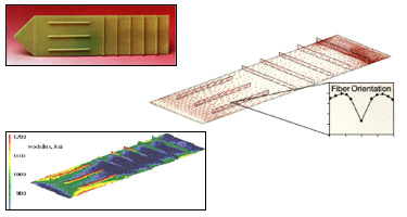
Figure 3. Top: Researchers use representative test plaques to test thermoplastic materials for a range of properties. These experimental data are compared to computer predictions and provide the basis for improving predictive models.
Middle: Process simulation predictions of fiber orientation can be represented visually.
Bottom: Predicted fiber orientation combined with material data can be used to predict the modulus of the test plaque.
To test the model predictions, the researchers entered the processing conditions used to mold the plaques into the currently available simulation programs, which then calculated dimensions, warpage, fiber orientation, and stiffness. After a number of iterations using different models, predicted values agreed with experimental results.
"Our current technique begins with the flow model to determine fiber orientation," says Pete Foss, the Staff Research Engineer responsible for analysis. "Then we use the structural package to predict failure based on fiber orientation and experimental data. The packages uses a material model that accounts for the anisotropy in the molded component."
The researchers have made tremendous strides in being able to predict the dimensional and mechanical performance of injection-molded parts. In fact, the commercial software programs Moldflow and ABAQUS now use the techniques developed at GM R&D. The researchers are continuing work on the predictive models and are also starting to implement the technology in plastic products.
At GM Powertrain, for example, engineers are using the new techniques to predict stiffness and strength of an injection-molded engine component. "The initial effort centers on reworking the existing part," says Cox. "If that's successful, they'll use the techniques we developed to build the next-generation component."
By Diane Kightlinger